Once you have scanned your maps, you are ready to begin working with them. First, you need to synchronize your scanned map with other spatial data. This is done by georeferencing, which aligns precise locations on your scanned map with the same locations on a specific coordinate system.
Data Requirements
In order to georeference each map, you need an existing spatially referenced vector dataset. When you’re selecting a dataset, consider that the dataset must:
• cover the same map area as the use and occupancy map that you are
georeferencing;
• be in the desired coordinate system for the survey area;
• and contain features that are present on the use and occupancy map. You will use these features to align your map. These features include road locations, water features, and political boundaries.
If you have selected your dataset correctly, it should line up with analogue maps. Ideally, you will use the same data to georeference the map as was used to produce the map.
Tutorial: Preparing for georeferencing
Before you start georeferencing, you need to set up ArcMap.
1. Click the Add button![]() to add the existing spatially referenced vector dataset. This ensures that the coordinate system of the map frame set correctly.
to add the existing spatially referenced vector dataset. This ensures that the coordinate system of the map frame set correctly.
2. Click the Add button to add the map image you want to georeference.
3. If you get a dialogue box asking if you want to create pyramids, click Yes.
| TIP: Pyramids allow faster viewing of the scanned map. However, it creates an .rrd file which may be quite large, so you may want to delete the associated .rrd file when you will have finished georeferencing. |
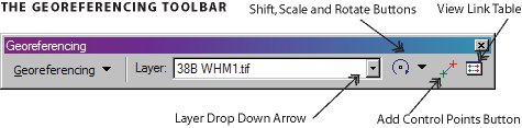
4. Add the georeferencing toolbar to ArcMap. From the
View menu, select Toolbars, and then select Georeferencing.
5. In the table of contents, locate the layer with your referenced dataset. Right- click on this layer and select Zoom to Layer.
6. From the georeferencing toolbar, click the Layer drop-down arrow. Select the layer corresponding to the map image that you want to georeference.
7. Select Georeferencing, then select Fit to Display. This displays the map image in the same area as the referenced dataset.
8. From the georeferencing toolbar, use the shift, scale and rotate buttons to move the map image to align with the referenced dataset.
Control Points
Georeferencing your map image involves two steps: identifying a set of control points, and correlating these control points on your scanned map to the spatially referenced dataset. After georeferencing, your scanned map will be accurately identified in real-world coordinates.
You can use a variety of features as control points, including street corners, road or stream intersections, corners of agricultural fields, political boundaries, rock formations and other more permanent and easily identifiable features on the landscape. Other features, such as
river bends, tend to change over time and may not align well with your spatially referenced data. It’s best to choose more permanent features as control points.
The control points are used to make a mathematical transformation that will translate the map image to the spatially correct location. The association between the control point of the map image and the corresponding control point on the spatially referenced data is known as
the ‘link’.
To ensure an accurate transformation, spread out the links over the entire image rather than concentrating them in one area. It’s best to place one link near each corner, with several more throughout the interior of the map. The total number of links you need will depend on how well the image aligns with the referenced data and the type of transformation you use.
Tutorial: Georeferencing
Now, let’s begin the georeferencing process:
1. Click the Add Control Points button![]() .
.
2. Add a link by clicking on a known location on the scanned map, then on a known location on the spatially referenced dataset. Use control points that exist on your scanned map and reference dataset.
| IMPORTANT: You must click the scanned map first, and then click the referenced dataset |
3. Repeat step 2 until you have added 6-12 links. The more links you add, the better your results will be. The number of links you need will depend on the type of transformation you are using.
| TIP: When you’re first getting started, add some rough control points to help with alignment. You can delete them when you have added more precise control points. |
Transformations
After creating your links, choose a transformation to permanently align the map image with the referenced dataset.
If you have only a few links, use a first-order transformation. The mathematical equation can exactly map each point to the target location. More complex distortions can be corrected by using higher-order transformations, which require more links.
In general, use:
| First-order transformation | When the raster dataset needs to be stretched, scaled, and rotated. |
| Second-order transformation | When the raster dataset must be bent or curved (for example, if you were georeferencing a dataset using a different coordinate system than was used to create the original map. |
Root Mean Square (RMS) Error
The root mean square error (RMS) is the difference between where “from point" ended up as opposed to the actual location that was originally specified—“to point" position. The total error is calculated by taking the root mean square (RMS) sum of all the residuals. This value describes how consistent the transformation is between the different control points. When the error is particularly large, you may want to remove and add control points to adjust the error.
Although the RMS error is a good assessment of the accuracy of the transformation, don’t confuse a low RMS error with an accurate georeference. For example, the transformation may still contain significant errors due to a poorly entered control point. The more control points of equal quality used, the more accurately the computer can convert the input data to output coordinates.
It is good practice to keep a text file to record your transformations and RMS error for all the maps in your particular project. This text file will be part of your metadata.
Tutorial: Transformations
1. Click the View Link Table button![]() to evaluate the transformation.
to evaluate the transformation.
2. Examine the residual error for each link and the total RMS error.
3. If necessary, delete control points by highlighting the point and clicking the Delete button![]() .
.
4. Choose the appropriate transformation: which one makes the scanned map line up best with the reference dataset?
5. When you are happy with the number and location of links, save your link table.
6. Click Georeferencing and select Update Georeferencing.
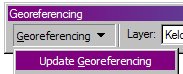
This saves the transformation information within the scanned map image and updates the associated .aux file with the georeferenced informatio
|
TIP: To permanently save the transformation, you can also choose to rectify the image. This will embed the spatial coordinates within a new raster file. TIP: If you decide you want to re-rectify the image, make a copy of the original dataset. As it will have no .aux file, you can bring it back into ArcMap as a fresh raster. You can then load the saved control points to begin where you left off, or you can start fresh. |
If you are referencing one raster to another raster (such as a scanned topographic map sheet), you may want to overlay the scanned map by removing the white areas. To do so:
1. From the table of contents, locate your scanned map image. Right-click on this layer and select Properties.
2. Select the Symbology tab.
3. Change the display to Classified with two classes.
4. Double-click on the white colour, and change this to No color. Click OK.
Note: if you’re using a colour image, you may consider using several values. You may also consider using transparency for your image to make it easier to see the base data. Transparency is located on the Display tab.